on technical rescue procedures.
THIS GUIDE IS NOT ALL INCLUSIVE!
It is intended to be used as a tool for training and for
quick field reference. Refer to current training manuals
and your department policies for detailed explanations.
There is no substitute for regular, quality, hands-on
training by a qualified instructor.
The techniques and procedures illustrated in this guide follow
NFPA standards and OSHA regulations as much as possible.
This guide can be used by rescuers at all skill levels but was
specifically developed for fully qualified technical rescue
technicians. Special operations are inherently dangerous and
serious injury or fatality may result from improper performance
of these techniques. The author accepts no responsibility for
damage, loss, injury or death resulting from information
contained in or omitted from this guide.
Thanks to the Phoenix Fire Department and everyone who helped
make this guide possible. Special thanks to my friend Ron Jamison for
helping to write this guide, Kathy Darrow for editing and to George
Drees, Ken Phillips and Jim Frank for great ideas and input.
This guide is dedicated to all those people who go the extra inch
every day to make themselves better rescuers.
This handbook is based on the Phoenix Fire Department and Arizona
State Fire Marshallチs Office technical rescue programs.
ISBN 0-9675238-4-2 Third Edition October 2003
Illustrations and text copyright c1999-2003 Tom Pendley. All rights reserved.
No reproduction, storage or transmission without written permission of the author.
Published by Desert Rescue Research. Photos by Tom Pendley and Glenn Speight.
Cover art, text layout and design by Glenn Speight.
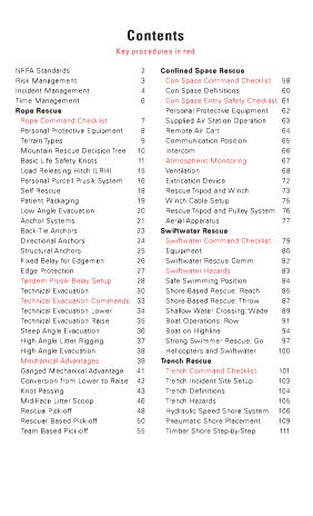
Key procedures in redNFPA Standards 2
Risk Management 3
Incident Management 4
Time Management 6
Rope Rescue
Rope Command Checklist 7
Personal Protective Equipment 8
Terrain Types 9
Mountain Rescue Decision Tree 10
Basic Life Safety Knots 11
Load Releasing Hitch (LRH) 15
Personal Purcell Prusik System 16
Self Rescue 18
Patient Packaging 19
Low Angle Evacuation 20
Anchor Systems 21
Back-Tie Anchors 23
Directional Anchors 24
Structural Anchors 25
Fixed Belay for Edgemen 26
Edge Protection 27
Tandem Prusik Belay Setup 28
Technical Evacuation 30
Technical Evacuation Commands 33
Technical Evacuation Lower 34
Technical Evacuation Raise 35
Steep Angle Evacuation 36
High Angle Litter Rigging 37
High Angle Evacuation 38
Mechanical Advantages 39
Ganged Mechanical Advantage 41
Conversion from Lower to Raise 42
Knot Passing 43
Mid-Face Litter Scoop 46
Rescue Pick-off 48
Rescuer Based Pick-off 50
Team Based Pick-off 55
Confined Space Rescue
Con Space Command Checklist 58
Con Space Definitions 60
Con Space Entry Safety Checklist 61
Personal Protective Equipment 62
Supplied Air Station Operation 63
Remote Air Cart 64
Communication Position 65
Intercom 66
Atmospheric Monitoring 67
Ventilation 68
Extrication Device 72
Rescue Tripod and Winch 73
Winch Cable Setup 75
Rescue Tripod and Pulley System 76
Aerial Apparatus 77
Swiftwater Rescue
Swiftwater Command Checklist 79
Equipment 80
Swiftwater Rescue Comm 82
Swiftwater Hazards 83
Safe Swimming Position 84
Shore-Based Rescue: Reach 85
Shore-Based Rescue: Throw 87
Shallow Water Crossing: Wade 89
Boat Operations: Row 91
Boat on Highline 94
Strong Swimmer Rescue: Go 97
Helicopters and Swiftwater 100
Trench Rescue
Trench Command Checklist 101
Trench Incident Site Setup 103
Trench Definitions 104
Trench Hazards 105
Hydraulic Speed Shore System 106
Pneumatic Shore Placement 109
Timber Shore Step-by-Step 111

Key procedures in redStructural Collapse
Structural Collapse Checklist 116
Task Level Checklist 117
SAR Marking System 119
Cut Station 121
Material Capacities and Weights 123
Airbag Operation 124
T Spot Shore 125
Ellis Clamps 126
Two Post Vertical Shore 127
Laced Post Shore 128
Alternate Door/Window Shore 129
Standard Door / Window Shore 130
60°and 45°Solid Sole Rakers 131
Flying Raker 134
Sloped Floor Shoring 135
Helicopter Operations
Helo Ops Command Checklist 139
Helicopter Flight Risk Score 140
Landing Zone Safety 141
Rescuer Safety 142
Power On Insertions 143
Longline Use Decision Tree 145
Longline/Short Haul Procedures 146
Capewell Release Mechanism 148
Litter Rigging for Longline 149
Emergency Procedures 150
Sling Loading Equipment 150
Rescue Medical Situations
Crush Syndrome 151
Suspension Trauma 152
Hypothermia 153
Appendices 154
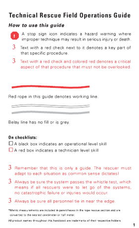
How to use this guide
A stop sign icon indicates a hazard warning where
improper technique may result in serious injury or death.
3 Text with a red check next to it denotes a key part of
that specific procedure.
3 Text with a red check and colored red denotes a critical
aspect of that procedure that must not be overlooked.
!Red rope in this guide denotes working line.
Belay line has no fill or is grey.
On checklists:
A black box indicates an operational level skill
A red box indicates a technician level skill
3Remember that this is only a guide. The rescuer must
adapt to each situation as common sense dictates!
3Always be sure the system passes the whistle test, which
means if all rescuers were to let go of the systems,
no catastrophic failure or injuries would occur.
3Always be sure all personnel tie in near the edge.
*Metric measurements are included in parentheses in the rope rescue section and are
converted to the nearest centimeter or half meter.
All product names throughout this handbook are trademarks of their respective holders.
1
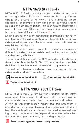
NFPA 1670 Standards
NFPA 1670 1999 edition is the current standard for technical
rescue operations. Skills and procedures in this guide are
categorized according to NFPA 1670 standards where
applicable. For example, a command checklist involves scene
size-up and hazard recognition. This is an awareness level skill
and will have an icon. High angle litter raising is a
technician level skill and will have a icon.
Some procedures are not specifically addressed in the NFPA
standard and the categorization is interpreted from similar
categorized procedures. An interpreted level will have an
asterisk next to the icon.
The intent is to make it easy for responders to assess
different situations appropriately and to train according to
standardized guidelines.
The general definitions of the 1670 operational levels are in
Appendix A. Refer to the NFPA 1670 document for complete
definitions in each area and for each skill or procedure.
The authority having jurisdiction has final say as to the
categorization of each procedure.
Awareness level skill Operational level skill
Technician level skill
NFPA 1983, 2001 Edition
NFPA 1983 is the U.S. Fire Service standard for life safety
rope and harnesses. It defines all rescue system
components, their construction, use, labeling and testing.
A two person system icon means that the procedure is
intended for two person loads and any component that will
bear the weight of two people must be rated for general use.
Light duty components may be part of the system when they
are used to support the weight of a single person.
Two person (general use) components
Safety is always our first concern
At the start of each operation, ask these questions;
1. What is the key problem?
2. What is our plan of action?
3. Why is that the safest plan?
4. What are the biggest risks that we need to watch out for?
5. What is your gut feeling about this plan?
Remember
_ We will risk our lives in a calculated way that is appropriate to
the situation to save savable lives
_ We will not risk our lives at all for that which is already lost
Communicate
_ Each operation must have a clearly defined leader
_ A decision on rescue or recovery strategy must be made
clear to everyone at the outset of every operation
_ Speak up if you see a problem no matter how small or
obvious it may seem
Re-evaluate strategy whenever appropriate
_ When new information becomes known
_ When a significant event occurs
_ After an extended time period has elapsed
Incident Management
Most technical rescue incidents are focused around a small
number of subjects and can be easily handled with a simple
Incident Command System (ICS) structure. Overall command
can be any officer but a rescue technician should assume an
operations level role and manage the technical rescue portion
of the incident.
Each discipline has a specific command checklist with key
tactical benchmarks. Use the checklist.
First Responders
_ Take command and size up
_ Focus on information gathering
_ Identify hazards
_ Be certain that the right resources are called early
_ Avoid activities marked in red on checklists and in text
Rescue Technician/Operations Officer (TSO)
_ Assume operations control
_ Review hazards and critical factors
_ Assist with the formation of incident action plan and
backup plan
_ Assign sectors and deploy resources
_ Keep command informed about all phases of the operation
_ Communicate with sectors and revise plans as needed
Rescue Technician/Sector Officer (i.e. Rescue Sector)
_ Clearly understand the action plan
_ Communicate the action plan to sector personnel
_ Supervise task level activities
_ Keep Operations Officer or Incident Commander updated on
a regular basis
Technical Sector Officer (TSO) is normally a term for the person
in charge of a group or sector (i.e. Rescue Sector). In some
cases the TSO may function as the overall rescue leader.
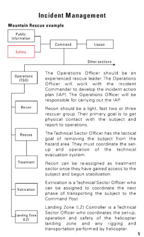
Mountain Rescue example
Public
Information
Safety
Command Liason
Other sectionsOperations
(TSO)
Recon
Rescue
Treatment
Extrication
Landing Zone
(LZ)
The Operations Officer should be an
experienced rescue leader. The Operations
Officer will work with the Incident
Commander to develop the incident action
plan (IAP). The Operations Officer will be
responsible for carrying out the IAP.
Recon should be a light, fast two or three
rescuer group. Their primary goal is to get
physical contact with the subject and
report to operations.
The Technical Sector Officer has the tactical
goal of removing the subject from the
hazard area. They must coordinate the set-
up and operation of the technical
evacuation system.
Recon can be re-assigned as treatment
sector once they have gained access to the
subject and begun stabilization.
Extrication is a Technical Sector Officer who
can be assigned to coordinate the next
phase of transporting the subject to the
Command Post.
Landing Zone (LZ) Controller is a Technical
Sector Officer who coordinates the set-up,
operation and safety of the helicopter
landing zone and any rigging and
transportation performed by helicopter.
5
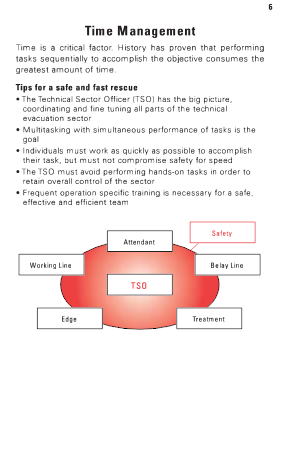
Time Management
Time is a critical factor. History has proven that performing
tasks sequentially to accomplish the objective consumes the
greatest amount of time.
Tips for a safe and fast rescue
_ The Technical Sector Officer (TSO) has the big picture,
coordinating and fine tuning all parts of the technical
evacuation sector
_ Multitasking with simultaneous performance of tasks is the
goal
_ Individuals must work as quickly as possible to accomplish
their task, but must not compromise safety for speed
_ The TSO must avoid performing hands-on tasks in order to
retain overall control of the sector
_ Frequent operation specific training is necessary for a safe,
effective and efficient team
Safety
Attendant
Working Line
Belay Line
TSO
Edge
Treatment
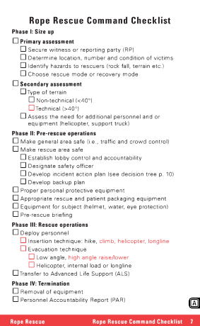
Phase I: Size up
Primary assessment
Secure witness or reporting party (RP)
Determine location, number and condition of victims
Identify hazards to rescuers (rock fall, terrain etc.)
Choose rescue mode or recovery mode
Secondary assessment
Type of terrain
Non-technical (<40°)
Technical (>40°)
Assess the need for additional personnel and or
equipment (helicopter, support truck)
Phase II: Pre-rescue operations
Make general area safe (i.e., traffic and crowd control)
Make rescue area safe
Establish lobby control and accountability
Designate safety officer
Develop incident action plan (see decision tree p. 10)
Develop backup plan
Proper personal protective equipment
Appropriate rescue and patient packaging equipment
Equipment for subject (helmet, water, eye protection)
Pre-rescue briefing
Phase III: Rescue operations
Deploy personnel
Insertion technique: hike, climb, helicopter, longline
Evacuation technique
Low angle, high angle raise/lower
Helicopter, internal load or longline
Transfer to Advanced Life Support (ALS)
Phase IV: Termination
Removal of equipment
Personnel Accountability Report (PAR)
Rope Rescue Rope Rescue Command Checklist
7
8
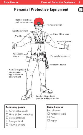
Personal Protective Equipment
Helmet with light
and chinstrap
Eye protection
Hydration system
Whistle
Class III harnessLeather gloves
Accessory
pouch
Personal carabiners
Descent device
Nomex
R
flight suit
or outerwear
appropriate for
environment
Leather hiking boots
provide ankle protection
Accessory pouch
Personal purcells
15 ft.(4.5m) webbing
Extra batteries
Energy food
Trauma shears
Radio harness
(not pictured)
Portable radio
Pen
Paper
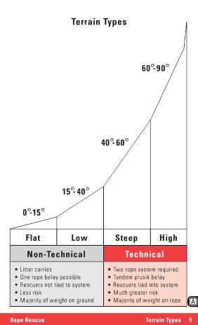
60°-90°
40°-60°
15°-40°
0°-15°
Flat Low Steep
Non-Technical Technical
High
_ Litter carries
_ One rope belay possible
_ Rescuers not tied to system
_ Less risk
_ Majority of weight on ground
_ Two rope system required
_ Tandem prusik belay
_ Rescuers tied into system
_ Much greater risk
_ Majority of weight on rope
Rope Rescue Terrain Types
9

10Mountain Rescue Decision Tree
Determine location
of subject
Send recon team by fastest means to
get physical contact with subject
Do not wait for helo support
Send in ground team
Rescue or recovery?
Body recovery is slow
Risk should be minimized
Determine terrain type
Form rescue plan
Low angle
Steep angle
High angle
YES
Is the patient
severely injured?
Is the patient
supported by a rope
or fall arrest system?
YES
NO
Consider mid-face
litter scoop
NO
Is the patient
severely injured?
NO
YES
Supported pickoff Unsupported pickoff
Evacuate to command post
by most appropriate means
High angle litter evac to safe LZ
or longline from safest LZ
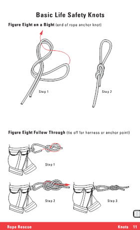
Figure Eight on a Bight (end of rope anchor knot)
Step 1Step 2
Figure Eight Follow Through (tie off for harness or anchor point)
Step 1
Step 2 Step 3
Rope Rescue Knots
11
12
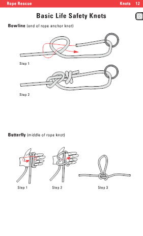
Basic Life Safety Knots
Bowline (end of rope anchor knot)
Step 1
Step 2
Butterfly (middle of rope knot)
Step 1 Step 2 Step 3
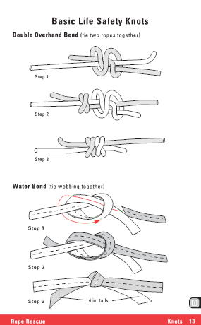
Double Overhand Bend (tie two ropes together)
Step 1
Step 2
Step 3
Water Bend (tie webbing together)
Step 1
Step 2
Step 3
4 in. tailsRope Rescue Knots
13
14
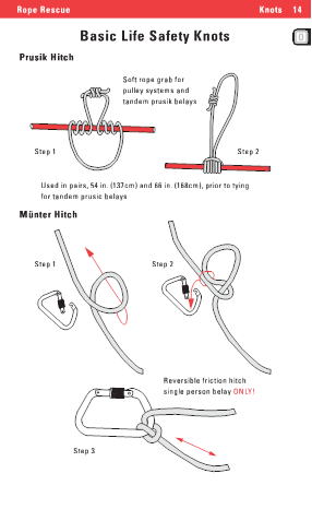
Basic Life Safety Knots
Prusik Hitch
Soft rope grab for
pulley systems and
tandem prusik belays
Step 1
Step 2
Used in pairs, 54 in. (137cm) and 66 in. (168cm), prior to tying
for tandem prusic belaysMunter Hitch
Step 1 Step 2
Reversible friction hitch
single person belay ONLY!
Step 3
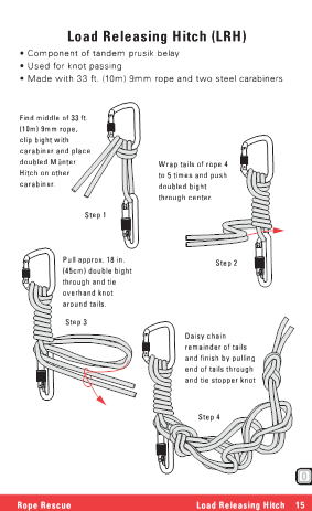
_ Component of tandem prusik belay
_ Used for knot passing
_ Made with 33 ft. (10m) 9mm rope and two steel carabiners
Find middle of 33 ft.
(10m) 9mm rope,
clip bight with
carabiner and place
doubled Munter
Hitch on other
carabiner.
Wrap tails of rope 4
to 5 times and push
doubled bight
through center.
Step 1
Pull approx. 18 in.
(45cm) double bight
through and tie
overhand knot
around tails.
Step 2
Step 3
Daisy chain
remainder of tails
and finish by pulling
end of tails through
and tie stopper knotStep 4
Rope Rescue Load Releasing Hitch
15
16
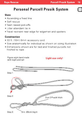
Personal Purcell Prusik System
Uses
_ Ascending a fixed line
_ Self rescue
_ Team based pick-offs
_ Litter attendant tie in
_ Travel restraint near edge for edgemen and spotters
Construction
_ 33 ft. (10m) 6mm accessory cord
_ Size anatomically for individual as shown on sizing illustration
_ Dimensions shown are for tied and finished purcells not
hitched to rope
Figure eight bend made
with bight and tail
Light use only!
Step 1
Step 23 on 2 Prusik hitch
Step 3
8 in. (20cm) bight
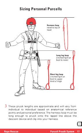
Harness loop
navel to top of
head
Long leg loop
cinched tight on
boot to navel
Short leg loop
cinched tight on
boot to upper
third of thigh3These prusik lengths are approximate and will vary from
individual to individual based on anatomical reference
points and personal preference. The harness loop must be
long enough to prusik onto the rappel line above the
descent device and clip into your harness.
Rope Rescue Purcell Prusik System
17
18Self Rescue
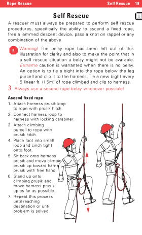
A rescuer must always be prepared to perform self rescue
procedures, specifically the ability to ascend a fixed rope,
free a jammed descent device, pass a knot on rappel or any
combination of the above.
Warning! The belay rope has been left out of this
illustration for clarity and also to make the point that in
a self rescue situation a belay might not be available.
Extremecaution is warranted when there is no belay.
An option is to tie a bight into the rope below the leg
purcell and clip it to the harness. Tie a new bight every
5 linear ft. (1.5m) of rope climbed and clip to harness.
3Always use a second rope belay whenever possible!
Ascend fixed rope
1. Attach harness prusik loop
to rope with prusik hitch.
2. Connect harness loop to
harness with locking carabiner.
3. Attach climbing
purcell to rope with
prusik hitch.
4. Place foot into small
loop and cinch tight
onto foot.
5. Sit back onto harness
prusik and move climbing
prusik up toward harness
prusik with free hand.
6. Stand up onto
climbing prusik and
move harness prusik
up as far as possible.
7. Repeat this process
until reaching
destination or until
problem is solved.
!
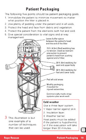
The following five points should be patient packaging goals.
1. Immobilize the patient to minimize movement no matter
what position the litter is placed in.
2. Use plenty of padding under the patient and in all voids.
3. Protect the head and face from debris and vegetation.
4. Protect the patient from the elements both hot and cold.
5. Give special consideration to vital signs and airway
management.
Leave buffer space
between the patientチs head
and the end of the litter
15 ft. (4.5m) (Red) webbing has
no tension. Used as restraint
precaution to prevent
patientチs head from pushing
against end of litter.
20 ft. (6m) webbing for
seat and upper body
30 ft. (9m) webbing for
feet and lower body
Pad all void areas
Modify packaging
if needed for
injured extremities
Commercially made strap
systems also work well
Cold weather
Use a three layer system.
1. Vapor barrier against skin.
2. Insulation layer.
3. Weather barrier.
Heat packs must be added
if the patient is hypothermic
or if the evacuation will take
longer than 30 minutes.3This illustration is but
one example of a
number of techniques
that can be used.
Rope Rescue Patient Packaging
19
20
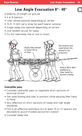
Low Angle Evacuation 0°- 40°
_ Majority of weight on ground
_ 4 to 6 bearers
_ Litter wheel optional depending on terrain
_ 15 ft. (4.5m) carry strap for each bearer optional
_ Single belay line optional depending on terrain
_ Use tandem prusik for belay
_ Do not load belay line or use to lower
Apply litter wheel
to head 1/3 rd
of litter
Six bearers are
used when the
wheel is not
practicalAttach 30 ft. (9m)
webbing to
litter head for
dynamic belay
Caterpillar pass
_ Consider caterpillar pass to negotiate short sections of
technical terrain
_ Get solid footing and stay in position while passing litter hand
to hand
_ Very effective on short sections of steep and high angle
obstacles
_ This is an effective technique but at least 10 or 12 bearers are
desirable to accommodate personnel rotation
_ Consider belay line
Definitions
_ Natural anchors: naturally occurring trees and rocks
_ Artificial anchors: anything placed by man including fire trucks
and structural members
_ Bombproof anchor: an anchor that you confidently believe will
hold the intended load and any potential impact force
unintentionally generated by the load
_ Marginal anchor: an anchor that you do not believe to be
bombproof
_ Single-point anchor: single point of origin
_ Multi-point anchor: a collection of marginal point anchors
connected into a bombproof anchor system
_ Back-tie anchor: a marginal anchor in a good location that is
linearly connected with a tensioning unit to a bombproof
anchor somewhere back from the edge
Concepts
_ Safety test all anchors in the direction of use with a force
comparable to the working load
_ Watch for signs of weakness or failure
_ Distribute force equally between all anchors in a multi-point
system
_ On multi-point anchors, keep the distributing link small to
minimize any potential impact force
_ Always try to have independent anchors for the working line
and belay line
_ Choose strong points like joints and corners on structural
members for anchors
_ Avoid mid-span anchor points on structural members if
possible
_ When using pre-sewn straps, prevent side loaded or tri-
loaded carabiners
Rope Rescue Anchor Systems
21
22
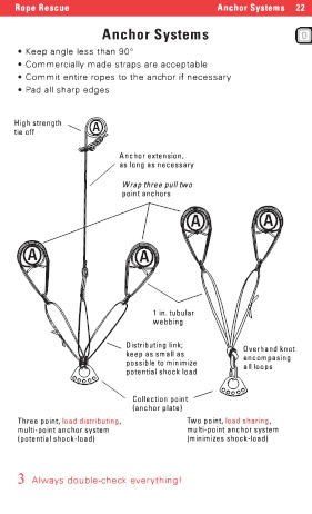
Anchor Systems
_ Keep angle less than 90°
_ Commercially made straps are acceptable
_ Commit entire ropes to the anchor if necessary
_ Pad all sharp edges
High strength
tie off
Anchor extension,
as long as necessary
Wrap three pull two
point anchors
1 in. tubular
webbing
Distributing link;
keep as small as
possible to minimize
potential shock load
Collection point
(anchor plate)
Overhand knot
encompasing
all loopsThree point, load distributing,
multi-point anchor system
(potential shock-load)
Two point, load sharing,
multi-point anchor system
(minimizes shock-load)
3Always double-check everything!
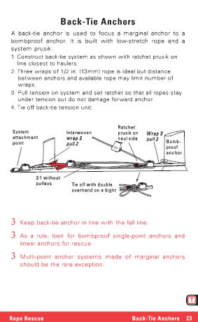
A back-tie anchor is used to focus a marginal anchor to a
bombproof anchor. It is built with low-stretch rope and a
system prusik.
1. Construct back-tie system as shown with ratchet prusik on
line closest to haulers.
2. Three wraps of 1/2 in. (13mm) rope is ideal but distance
between anchors and available rope may limit number of
wraps.
3. Pull tension on system and set ratchet so that all ropes stay
under tension but do not damage forward anchor.
4. Tie off back-tie tension unit.
System
attachment
point
Interwoven
wrap 3
pull 2
Ratchet
prusik on
haul side
Wrap 3
pull 2Bomb-
proof
anchor
3:1 without
pulleys
Tie off with double
overhand on a bight
3Keep back-tie anchor in line with the fall line.
3As a rule, look for bombproof single-point anchors and
linear anchors for rescue.
3Multi-point anchor systems made of marginal anchors
should be the rare exception.
Rope Rescue Back-Tie Anchors
23
24
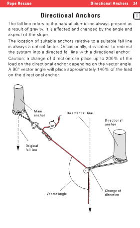
Directional Anchors
The fall line refers to the natural plumb line always present as
a result of gravity. It is affected and changed by the angle and
aspect of the slope.
The location of suitable anchors relative to a suitable fall line
is always a critical factor. Occasionally, it is safest to redirect
the system into a directed fall line with a directional anchor.
Caution: a change of direction can place up to 200% of the
load on the directional anchor depending on the vector angle.
A 90°vector angle will place approximately 140% of the load
on the directional anchor.
Main
anchorDirected fall line
Directional
anchor
Original
fall line
Vector angle
Change of
direction
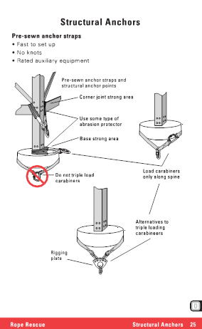
Pre-sewn anchor straps
_ Fast to set up
_ No knots
_ Rated auxiliary equipment
Pre-sewn anchor straps and
structural anchor points
Corner joint strong area
Use some type of
abrasion protector
Base strong area
Do not triple load
carabiners
Load carabiners
only along spine
Alternatives to
triple loading
carabineers
Rigging
plateRope Rescue Structural Anchors
25
26
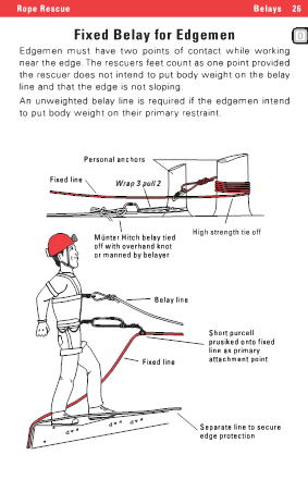
Fixed Belay for Edgemen
Edgemen must have two points of contact while working
near the edge. The rescuers feet count as one point provided
the rescuer does not intend to put body weight on the belay
line and that the edge is not sloping.
An unweighted belay line is required if the edgemen intend
to put body weight on their primary restraint.
Personal anchors
Fixed line
Wrap 3 pull 2
Munter Hitch belay tied
off with overhand knot
or manned by belayer
High strength tie offBelay line
Fixed line
Short purcell
prusiked onto fixed
line as primary
attachment point
Separate line to secure
edge protection
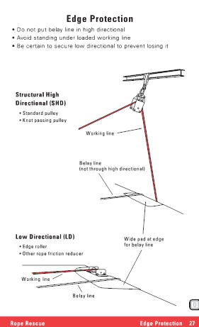
_ Do not put belay line in high directional
_ Avoid standing under loaded working line
_ Be certain to secure low directional to prevent losing it
Structural High
Directional (SHD)
_ Standard pulley
_ Knot passing pulley
Working line
Belay line
(not through high directional)
Low Directional (LD)
_ Edge roller
_ Other rope friction reducer
Wide pad at edge
for belay line
Working lineBelay line
Rope Rescue Edge Protection
27
28
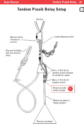
Tandem Prusik Belay Setup
Anchor
Munter Hitch
closest to
anchor
Clip end of belay
line into anchor
sling
Load releasing hitch
54 in. (1.4m) 8 mm
system prusik closest
to carabiner spine
66 in. (1.7m) 8 mm
system prusik
Dress prusiks
down snugly
!Minimize slack in
belay system
Rescue package
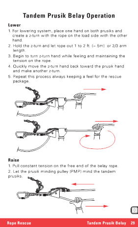
Lower
1. For lowering system, place one hand on both prusiks and
create a z-turn with the rope on the load side with the otherhand.
2. Hold the z-turn and let rope out 1 to 2 ft. (~.5m) or 2/3 arm
length.
3. Begin to turn z-turn hand while feeling and maintaining the
tension on the rope.
4. Quickly move the z-turn hand back toward the prusik hand
and make another z-turn.
5. Repeat this process always keeping a feel for the rescue
package.
Raise
1. Pull constant tension on the free end of the belay rope.
2. Let the prusik minding pulley (PMP) mind the tandem
prusiks.