THIS GUIDE IS NOT ALL INCLUSIVE!
It is intended to be used as a tool for training and for quick field reference.
Refer to current training manuals and your department policies for detailed explanations.
There is no substitute for regular, quality, hands-on training by a qualified instructor.
The techniques and procedures illustrated in this guide follow NFPA standards and OSHA regulations as much as possible.
This guide can be used by rescuers at all skill levels but was specifically developed for fully qualified technical rescue technicians.
Special operations are inherently dangerous and serious injury or fatality may result from improper performance of these techniques.
The author accepts no responsibility for damage, loss, injury or death resulting from information contained in or omitted from this guide.
Thanks to the Phoenix Fire Department and everyone who helped make this guide possible.
Special thanks to my friend Ron Jamison for helping to write this guide, Kathy Darrow for editing and to George Drees, Ken Phillips and Jim Frank for great ideas and input.
This guide is dedicated to all those people who go the extra inch every day to make themselves better rescuers.
This handbook is based on the Phoenix Fire Department and Arizona State Fire Marshallチs Office technical rescue programs.
ISBN 0-9675238-4-2
Third Edition October 2003
Illustrations and text copyright c1999-2003 Tom Pendley.
All rights reserved.
No reproduction, storage or transmission without written permission of the author.
Published by Desert Rescue Research. Photos by Tom Pendley and Glenn Speight.
Cover art, text layout and design by Glenn Speight.

Key procedures in red
NFPA Standards 2
Risk Management 3
Incident Management 4
Time Management 6
Rope Rescue
Rope Command Checklist 7
Personal Protective Equipment 8
Terrain Types 9
Mountain Rescue Decision Tree 10
Basic Life Safety Knots 11
Load Releasing Hitch (LRH) 15
Personal Purcell Prusik System 16
Self Rescue 18
Patient Packaging 19
Low Angle Evacuation 20
Anchor Systems 21
Back-Tie Anchors 23
Directional Anchors 24
Structural Anchors 25
Fixed Belay for Edgemen 26
Edge Protection 27
Tandem Prusik Belay Setup 28
Technical Evacuation 30
Technical Evacuation Commands 33
Technical Evacuation Lower 34
Technical Evacuation Raise 35
Steep Angle Evacuation 36
High Angle Litter Rigging 37
High Angle Evacuation 38
Mechanical Advantages 39
Ganged Mechanical Advantage 41
Conversion from Lower to Raise 42
Knot Passing 43
Mid-Face Litter Scoop 46
Rescue Pick-off 48
Rescuer Based Pick-off 50
Team Based Pick-off 55
Confined Space Rescue
Con Space Command Checklist 58
Con Space Definitions 60
Con Space Entry Safety Checklist 61
Personal Protective Equipment 62
Supplied Air Station Operation 63
Remote Air Cart 64
Communication Position 65
Intercom 66
Atmospheric Monitoring 67
Ventilation 68
Extrication Device 72
Rescue Tripod and Winch 73
Winch Cable Setup 75
Rescue Tripod and Pulley System 76
Aerial Apparatus 77
Swiftwater Rescue
Swiftwater Command Checklist 79
Equipment 80
Swiftwater Rescue Comm 82
Swiftwater Hazards 83
Safe Swimming Position 84
Shore-Based Rescue: Reach 85
Shore-Based Rescue: Throw 87
Shallow Water Crossing: Wade 89
Boat Operations: Row 91
Boat on Highline 94
Strong Swimmer Rescue: Go 97
Helicopters and Swiftwater 100
Trench Rescue
Trench Command Checklist 101
Trench Incident Site Setup 103
Trench Definitions 104
Trench Hazards 105
Hydraulic Speed Shore System 106
Pneumatic Shore Placement 109
Timber Shore Step-by-Step 111
Key procedures in red
Structural Collapse
Structural Collapse Checklist 116
Task Level Checklist 117
SAR Marking System 119
Cut Station 121
Material Capacities and Weights 123
Airbag Operation 124
T Spot Shore 125
Ellis Clamps 126
Two Post Vertical Shore 127
Laced Post Shore 128
Alternate Door/Window Shore 129
Standard Door / Window Shore 130
60°and 45°Solid Sole Rakers 131
Flying Raker 134
Sloped Floor Shoring 135
Helicopter Operations
Helo Ops Command Checklist 139
Helicopter Flight Risk Score 140
Landing Zone Safety 141
Rescuer Safety 142
Power On Insertions 143
Longline Use Decision Tree 145
Longline/Short Haul Procedures 146
Capewell Release Mechanism 148
Litter Rigging for Longline 149
Emergency Procedures 150
Sling Loading Equipment 150
Rescue Medical Situations
Crush Syndrome 151
Suspension Trauma 152
Hypothermia 153
Appendices 154
Command Checklist 58
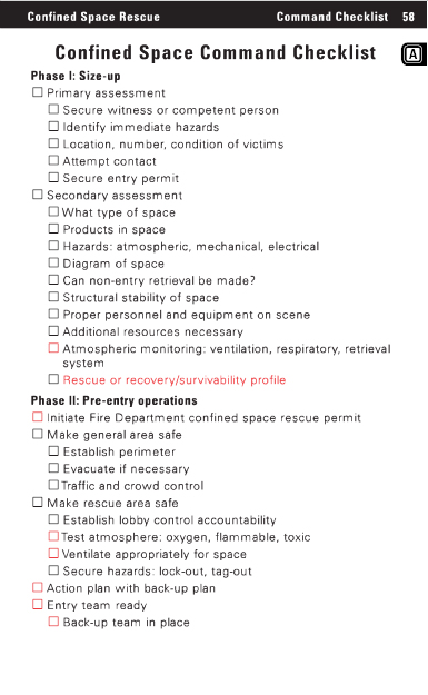
Confined Space Command Checklist
Phase I: Size-up
Primary assessment
Secure witness or competent person
Identify immediate hazards
Location, number, condition of victims
Attempt contact
Secure entry permit
Secondary assessment
What type of space
Products in space
Hazards: atmospheric, mechanical, electrical
Diagram of space
Can non-entry retrieval be made?
Structural stability of space
Proper personnel and equipment on scene
Additional resources necessary
Atmospheric monitoring: ventilation, respiratory, retrieval system
Rescue or recovery/survivability profile
Phase II: Pre-entry operations
Initiate Fire Department confined space rescue permit
Make general area safe
Establish perimeter
Evacuate if necessary
Traffic and crowd control
Make rescue area safe
Establish lobby control accountability
Test atmosphere: oxygen, flammable, toxic
Ventilate appropriately for space
Secure hazards: lock-out, tag-out
Action plan with back-up plan
Entry team ready
Back-up team in place
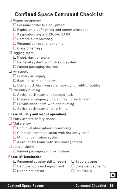
Proper equipment
Personal protective equipment
Explosion proof lighting and communications
Respiratory system (SCBA, SABA)
Remote air monitoring
Personal atmospheric monitor
Class 3 harness
Rigging team
Tripod, davit or crane
Retrieval system with back-up system
Patient packaging devices
Air supply
Primary air supply
Back-up team air supply
Utility truck high pressure hook-up for refill of bottles
Pre-entry briefing
Advise each team of expected task
Discuss emergency procedures for each team
Provide each team with site briefing
Advise each team of time limits
Phase III: Entry and rescue operations
Entry system safety check
Make entry
Continual atmospheric monitoring
Constant communication with the entry team
Monitor ventilation system
Assist entry team with line management
Locate victim
Patient packaging and extrication
Phase IV: Termination
Personnel accountability report
Secure scene
Remove tools and equipment
Consider debriefing
Decontamination
Call OSHA
Confined Space Rescue
Command Checklist 59
Definitions 60
Confined Space Rescue
OSHA 29 CFR 1910.146 applies to general industry and the rescue service.
An OSHA confined space is defined as:
1. A space large enough for personnel to physically enter.
2. Not designed for continuous employee occupancy.
3. An area with limited entry and egress.
A confined space permit is required if the space has one or more of the following hazards:
1. Atmospheric hazards.
2. Configuration hazard.
3. Engulfment hazard.
4. Any other recognized hazard.
Acceptable entry conditions
Oxygen between: 19.5% and 22.5%
Lower explosive limit (LEL): <10% of the LEL
Toxicity: < IDLH
Immediately dangerous to life and health (IDLH)
Heat stress can quickly become a life threatening hazard. Rotate crews frequently.
3 Take the extra time to carefully manage all lines.
3 Be sure to have the lobby/attendant take up all lines as the entry team returns to the outside.
3 Expect the atmosphere to suddenly become unsafe.
3 Monitor the atmosphere continuously.
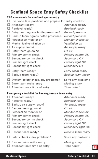
TSO commands for confined space entry
Everyone take positions and prepare for entry checklist
Attendant ready? Attendant Ready
Retrieval ready? Retrieval ready
Entry team egress bottle pressures? Record pressure
Backup team egress bottle pressures? Record pressure
Personal air monitor on Monitor checks ok
Mechanical ventilation on Ventilation on
Air supply ready? Air supply ready
Entry team go on air On air
Primary comm check Primary comm OK
Secondary comm check Secondary OK
Primary light check Primary light OK
Secondary light check Secondary OK
Entry team ready? Entry team ready
Backup team ready? Backup team ready
System safety check, any problems? Solve any problems
Entry team make entry Making entry
Attendant note time of entry Time noted
Emergency checklist for backup/rescue team entry
Attendant ready? Attendant ready
Retrieval ready? Retrieval ready
Backup air supply ready? Air supply ready
Rescue team go on air. On air
Personal air monitor on. Monitor checks ok
Primary comm check. Primary comm OK
Secondary comm check. Secondary OK
Primary light check. Primary light OK
Secondary light check. Secondary light OK
Rescue team ready? Rescue team ready
Safety checks, any problems? Solve any problems
Rescue team make entry. Making entry
Attendant note time of entry. Time noted
Confined Space
Safety Checklist 61
Personal Protective Equipment 62
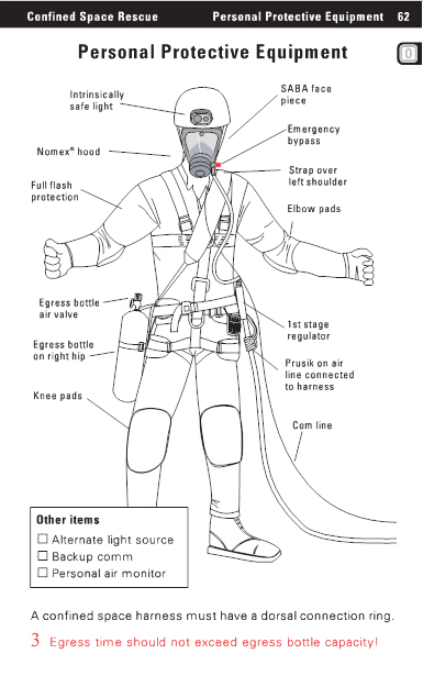
Personal Protective Equipment
Intrinsically
safe light
SABA face piece
Nomex R hood
Full flash protection
Emergency bypass
Strap over left shoulder
Elbow pads
Egress bottle air valve
Egress bottle on right hip
Knee pads
1st stage regulator
Prusik on air line connected to harness
Com line
Other items
Alternate light source
Backup comm
Personal air monitor
A confined space harness must have a dorsal connection ring.
3 Egress time should not exceed egress bottle capacity!
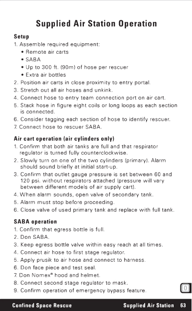
Setup
1. Assemble required equipment:
_ Remote air carts
_ SABA
_ Up to 300 ft. (90m) of hose per rescuer
_ Extra air bottles
2. Position air carts in close proximity to entry portal.
3. Stretch out all air hoses and unkink.
4. Connect hose to entry team connection port on air cart.
5. Stack hose in figure eight coils or long loops as each section is connected.
6. Consider tagging each section of hose to identify rescuer.
7. Connect hose to rescuer SABA.
Air cart operation (air cylinders only)
1. Confirm that both air tanks are full and that respirator regulator is turned fully counterclockwise.
2. Slowly turn on one of the two cylinders (primary).
Alarm should sound briefly at initial start-up.
3. Confirm that outlet gauge pressure is set between 60 and 120 psi.
without respirators attached (pressure will vary between different models of air supply cart).
4. When alarm sounds, open valve of secondary tank.
5. Alarm must stop before proceeding.
6. Close valve of used primary tank and replace with full tank.
SABA operation
1. Confirm that egress bottle is full.
2. Don SABA.
3. Keep egress bottle valve within easy reach at all times.
4. Connect air hose to first stage regulator.
5. Apply prusik to air hose and connect to harness.
6. Don face piece and test seal.
7. Don Nomex R hood and helmet.
8. Connect second stage regulator to mask.
9. Confirm operation of emergency bypass feature.
Confined Space Rescue
Supplied Air Station 63
Remote Air Supply Cart 64
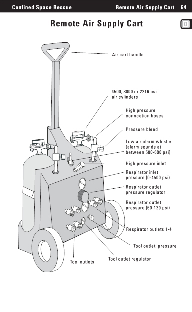
Remote Air Supply Cart
Air cart handle
4500, 3000 or 2216 psi air cylinders
High pressure connection hoses
Pressure bleed
Low air alarm whistle(alarm sounds at between 500-600 psi)
High pressure inlet
Respirator inlet pressure (0-4500 psi)
Respirator outlet pressure regulator
Respirator outlet
pressure (60-120 psi)
Respirator outlets 1-4
Tool outlet pressure
Tool outlets
Tool outlet regulator
Setup
1. Position intercom kit in close proximity to entry portal (watch for hazardous atmosphere near the portal).
2. Stretch out comm line and un-kink.
3. Connect required number of comm line sections together.
4. If connectors will not lock into position, clean O ring mating surfaces with moist rag.
5. Connect female end of comm line to command module.
6. Stack comm line so as to inhibit kinking problems.
7. Connect operator head set to operator connection port on command module.
8. Determine whether entry team rescuer will use headset or ear piece and throat mike.
9. Connect male end of comm line to rescuer.
10. Secure comm line to rescuer harness with small loop of slack between harness and end connection.
11. Install batteries in command module and test.
Operation
1. The attendant is required to maintain constant communication with the entry team.
2. The attendant can relay information to the TSO.
3. The TSO should not wear the headset unless it is a single side headset.
4. Adjust volume controls, as necessary.
Backup plan
1. The backup team must have a dedicated communication and air system.
2. Repeated contacts with entry team should be made via radio.
3. Test radio at junction points.
4. If communications fail, attempt brief troubleshooting and whistle or air horn signals (one long blast, repeat if necessary).
5. If communications cannot be re-established within one minute, send in the backup team.
Confined Space Rescue
Communication Sector 65
Intercom System 66
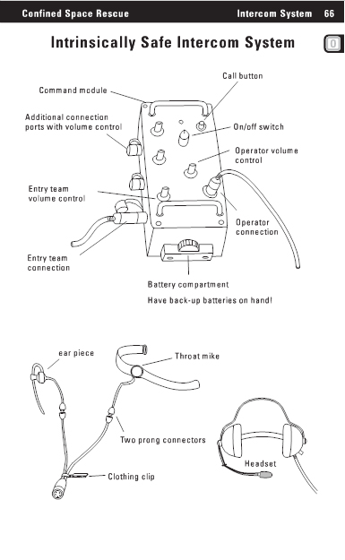
Intrinsically Safe Intercom System
Call button
Command module
Additional connection ports with volume control
On/off switch
Operator volume control
Entry team volume control
Operator connection
Entry team connection
Battery compartment
Have back-up batteries on hand!
ear piece
Throat mike
Two prong connectors
Clothing clip
Headset
Principles of air monitoring
_ Calibrate and span meter according to department procedures.
_ If oxygen level is not normal, flammability readings will be affected.
_ Spaces may have stratified atmospheres, all levels of space must be monitored.
_ Allow for air intake in sampling hose at approximately 1 second per foot of hose.
_ 10,000 parts per million = 1%.
_ If oxygen reading is 1% low and it is being displaced by a contaminant, up to 5% of the total atmosphere may consist of that contaminant (50,000 ppm).
_ Physical properties of a product can be found in the NIOSH pocket guide or MSDS.
_ The calculated molecular weight of air is 29.
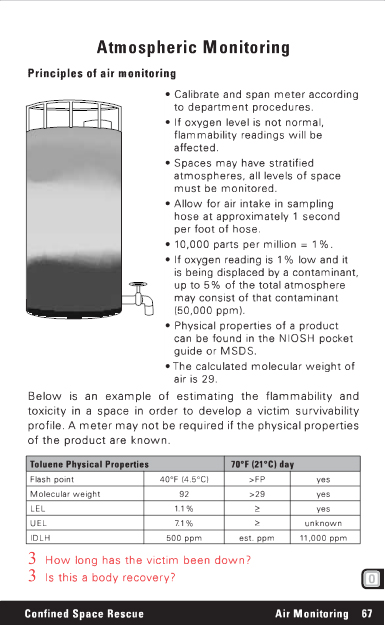
Below is an example of estimating the flammability and toxicity in a space in order to develop a victim survivability profile.
A meter may not be required if the physical properties of the product are known.
Toluene Physical Properties
70°F (21°C) day
Flash point
40°F (4.5°C) >FP yes
Molecular weight
92 >29 yes
LEL
1.1% 3 yes
UEL
7.1% 3 unknown
IDLH
500 ppm
est. ppm
11,000 ppm
3 How long has the victim been down?
3 Is this a body recovery?
Confined Space Rescue
Air Monitoring 67
Ventilation68
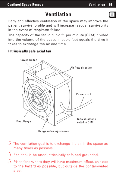
Ventilation
Early and effective ventilation of the space may improve the patient survival profile and will increase rescuer survivability in the event of respirator failure.
The capacity of the fan in cubic ft. per minute (CFM) divided into the volume of the space in cubic feet equals the time it takes to exchange the air one time.
Intrinsically safe axial fan
Power switch
Air flow direction
Power cord
Duct flange
Individual fans rated in CFM
Flange retaining screws
3 The ventilation goal is to exchange the air in the space as many times as possible.
3 Fan should be rated intrinsically safe and grounded.
3 Place fans where they will have maximum effect, as close to the hazard as possible, but outside the contaminated area.

The axial fan is capable of positive and negative ventilation depending upon which side the duct is connected. The fan shown is only able to exhaust with the 16 in. duct. A soft reducer coupling is not suitable for exhaust ventilation.
Know your equipment.
Intrinsically safe axial fan
16 in. flexible duct
Soft reducer coupling
8 in. flexible duct
Manhole cover
Caution:
bends in ductwork will reduce the rated capacity of the fan used
Saddle vent
Saddle vent retaining bracket
Additional duct can be added to increase ventilation effectiveness
3 Be extremely cautious when ventilating spaces with known flammable atmospheres due to the potential of the exhaust component reaching an ignition source.
Confined Space Rescue
Ventilation 69
Ventilation 70
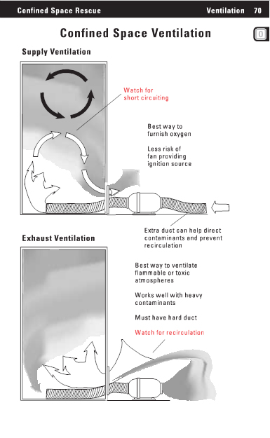
Confined Space Ventilation
Supply Ventilation
Watch for short circuiting
Best way to furnish oxygen
Less risk of fan providing ignition source
Exhaust Ventilation
Extra duct can help direct contaminants and prevent recirculation
Best way to ventilate flammable or toxic atmospheres
Works well with heavy contaminants
Must have hard duct
Watch for recirculation
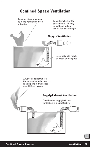
Look for other openings to make ventilation more effective
Consider whether the contaminant is heavy or light and set up ventilation accordingly
Supply Ventilation
Use ducting to reach all areas of the space
Always consider where the contaminated exhaust is going and if it will pose an additional hazard
Supply/Exhaust Ventilation
Combination supply/exhaust ventilation is most effective
Confined Space Rescue
Ventilation 71
Extrication Device 72
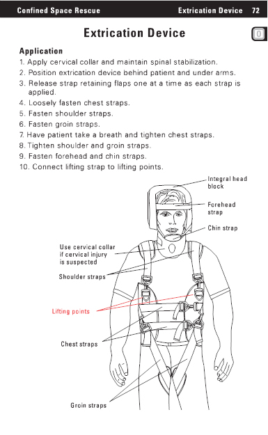
Extrication Device
Application
1. Apply cervical collar and maintain spinal stabilization.
2. Position extrication device behind patient and under arms.
3. Release strap retaining flaps one at a time as each strap is applied.
4. Loosely fasten chest straps.
5. Fasten shoulder straps.
6. Fasten groin straps.
7. Have patient take a breath and tighten chest straps.
8. Tighten shoulder and groin straps.
9. Fasten forehead and chin straps.
10. Connect lifting strap to lifting points.
Integral head block
Forehead strap
Chin strap
Use cervical collar if cervical injury is suspected
Shoulder straps
Lifting points
Chest straps
Groin straps
Setup
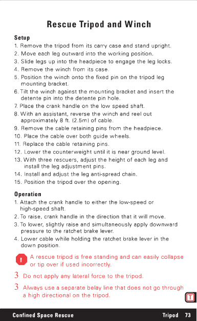
1. Remove the tripod from its carry case and stand upright.
2. Move each leg outward into the working position.
3. Slide legs up into the headpiece to engage the leg locks.
4. Remove the winch from its case.
5. Position the winch onto the fixed pin on the tripod leg mounting bracket.
6. Tilt the winch against the mounting bracket and insert the detente pin into the detente pin hole.
7. Place the crank handle on the low speed shaft.
8. With an assistant, reverse the winch and reel out approximately 8 ft. (2.5m) of cable.
9. Remove the cable retaining pins from the headpiece.
10. Place the cable over both guide wheels.
11. Replace the cable retaining pins.
12. Lower the counterweight until it is near ground level.
13. With three rescuers, adjust the height of each leg and install the leg adjustment pins.
14. Install and adjust the leg anti-spread chain.
15. Position the tripod over the opening.
Operation
1. Attach the crank handle to either the low-speed or high-speed shaft.
2. To raise, crank handle in the direction that it will move.
3. To lower, slightly raise and simultaneously apply downward pressure to the ratchet brake lever.
4. Lower cable while holding the ratchet brake lever in the down position.
A rescue tripod is free standing and can easily collapse or tip over if used incorrectly.
3 Do not apply any lateral force to the tripod.
3 Always use a separate belay line that does not go through a high directional on the tripod.
Confined Space Rescue
Tripod
73
Tripod 74
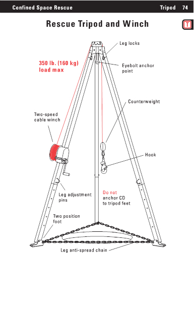
Rescue Tripod and Winch
Leg locks
350 lb. (160 kg)
load max
Eyebolt anchor point
Counterweight
Two-speed cable winch
Hook
Leg adjustment pins
Two position foot
Do not anchor CD to tripod
feetLeg anti-spread chain
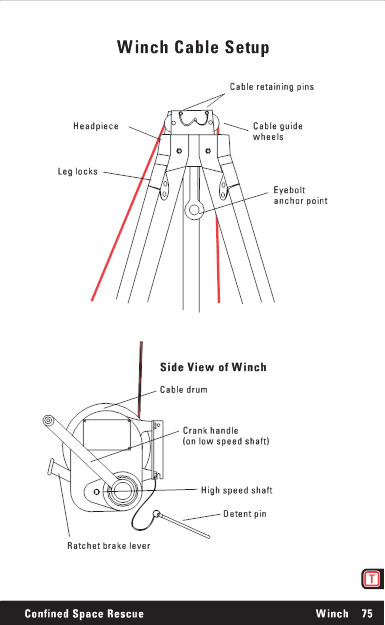
Cable retaining pins
Headpiece
Cable guide wheels
Leg locks
Eyebolt anchor point
Side View of Winch
Cable drum
Crank handle
(on low speed shaft)
High speed shaft
Detent pin
Ratchet brake lever
Confined Space Rescue
Winch 75
Tripod and Pulley System 76
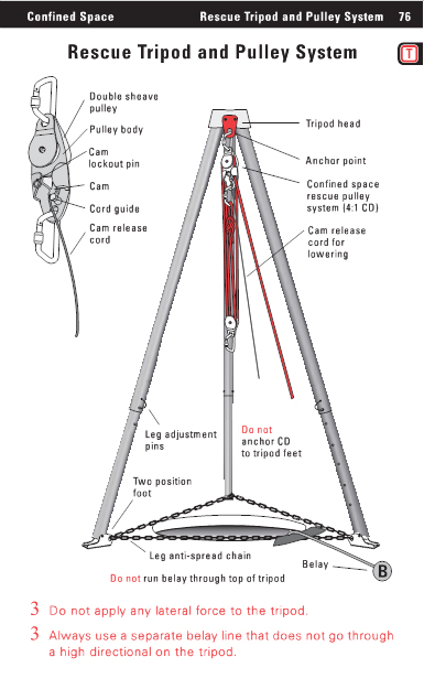
Rescue Tripod and Pulley System
Double sheave pulley
Pulley body
Cam lockout pin
Cam
Cord guide
Cam release cord
Tripod head
Anchor point
Confined space rescue pulley system (4:1 CD)
Cam release cord for lowering
Leg adjustment pins
Two position foot
Do not
anchor CD to tripod feet
Leg anti-spread chain
Belay
Do not run belay through top of tripod
3 Do not apply any lateral force to the tripod.
3 Always use a separate belay line that does not go through a high directional on the tripod.
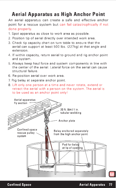
An aerial apparatus can create a safe and effective anchor point for a rescue system but can fail catastrophically if not done properly.
1. Spot apparatus as close to work area as possible.
2. Position tip of aerial directly over intended work area.
3. Check tip capacity chart on turn table to ensure that the aerial can support at least 500 lbs. (227kg) at that angle and extension.
4. If within capacity, return aerial to ground and rig anchor point and system.
5. Always keep haul force and system components in line with the center of the aerial. Lateral force on the aerial can cause structural failure.
6. Re-position aerial over work area.
7. Rig belay at separate anchor point.
8. Lift only one person at a time and never rotate, extend or retract the aerial with a person on the system. The aerial is to be used as an anchor point only!
Aerial apparatus fly section
20 ft. (6m) 1 in.
tubular webbing
Anchor plate
Confined space rescue pulley system
Belay anchored separately from the high anchor point
Pad for belay at lip of opening
Confined Space
Aerial Apparatus 77
Aerial Apparatus 78
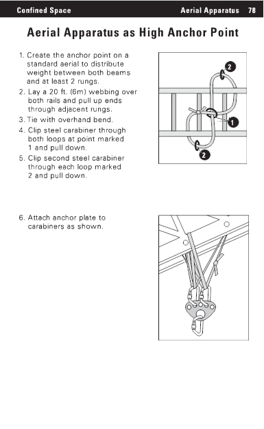
Aerial Apparatus as High Anchor Point
1. Create the anchor point on a standard aerial to distribute weight between both beams and at least 2 rungs.
2. Lay a 20 ft. (6m) webbing over both rails and pull up ends through adjacent rungs.
3. Tie with overhand bend.
4. Clip steel carabiner through both loops at point marked 1 and pull down.
5. Clip second steel carabiner through each loop marked 2 and pull down.
6. Attach anchor plate to carabiners as shown.